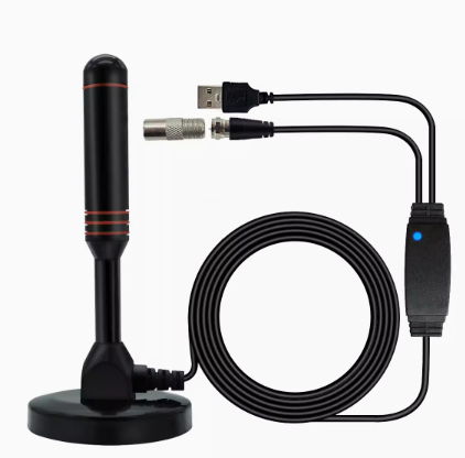
Introduction to GPS antenna
Introduction to GPS antenna
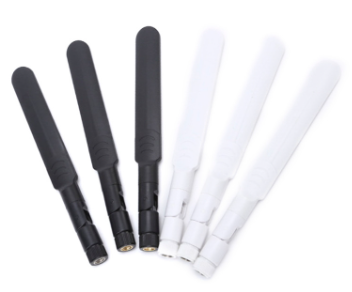
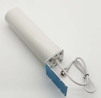
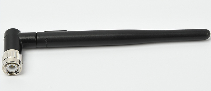
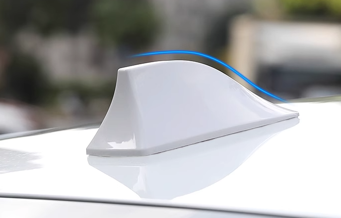
GPS antenna refers to the antenna used for positioning or navigation by receiving satellite signals.
The GPS satellite signals are L1 and L2, and the frequencies are 1575.42MHz and 1228MHz, respectively.
The signal is circularly polarized. The signal is generally around 166-DBM, which is a weak signal.
Classification of GPS antennas
⒈In terms of polarization, GPS antennas are divided into vertical polarization and circular polarization.
With current technology, the effect of vertical polarization is not as good as circular polarization. Therefore, except for special circumstances, GPS antennas
Use circular polarization.
⒉In terms of placement, GPS antennas are divided into internal antennas and external antennas.
The assembly location of the antenna is also very important. Early GPS handsets mostly used flipped antennas. At this time, the antenna and the whole machine
The interior is basically isolated, and EMI hardly affects it, and the satellite collection effect is very good. Now with the trend of miniaturization, GPS antennas are used more
Use built-in. At this time, the antenna must be above all metal components, and the inside of the shell must be electroplated and well grounded, far away from EMI interference sources, such as
CPU, SDRAM, SD card, crystal oscillator, DC/DC.
The application of car GPS will become more and more common. And the casing of the car, especially the car anti-explosion film, will cause the GPS signal to be strict.
Heavy obstruction. An external antenna with a magnet (which can be attached to the roof of the car) is very necessary for car GPS.
The structure of the GPS antenna
At present, the vast majority of GPS antennas are right-handed polarized ceramic media, and its components are: ceramic antennas, low-noise signals
Modules, cables, connectors.
Among them, ceramic antennas are also called passive antennas, dielectric antennas, and PATCH. It is the core technology of GPS antennas. A
The signal receiving ability of the GPS antenna is mostly determined by the composition of its ceramic part.
The low noise signal module is also called LNA, which is the part that amplifies and filters the signal. The selection of its components is also very heavy
Yes, otherwise it will increase the reflection loss of the GPS signal and cause excessive noise.
The selection of cables should also be based on reducing reflections to ensure impedance matching.
Main factors affecting GPS antenna
The main factors affecting the performance of GPS antennas are as follows:
1. Ceramic slices: The quality of ceramic powder and the sintering process directly affect its performance. The ceramic slices currently in use on the market are mainly
If it is 25×25, 18×18, 15×15, 12×12. The larger the area of the ceramic sheet, the larger the dielectric constant and the higher the resonance frequency.
The better the acceptance effect. Ceramic sheets are mostly square design to ensure that the resonance in the XY direction is basically the same, so as to achieve
The effect of evenly collecting stars.
2. Silver layer: The silver layer on the surface of the ceramic antenna can affect the antenna resonant frequency. The ideal GPS ceramic chip frequency point accurately falls on
1575.42MHz, but the antenna frequency is very susceptible to the surrounding environment, especially if it is assembled in the whole machine, it must be adjusted
The shape of the surface coating can be adjusted to keep the frequency at 1575.42MHz. Therefore, the GPS manufacturer must match the antenna when purchasing the antenna.
Cooperate with antenna manufacturers to provide complete machine samples for testing.
3. Feed point: The ceramic antenna collects the resonance signal through the feed point and sends it to the back end. Due to the antenna impedance matching,
The feed point is generally not in the center of the antenna, but slightly adjusted in the XY direction. This impedance matching method is simple and
There is no increase in cost. Only moving in a single axis direction is called a single-biased antenna, and moving in both axes is called a double-biased antenna.
4. Amplification circuit: The shape and area of the PCB that carries the ceramic antenna. Because GPS has the characteristic of rebounding when it touches the ground, it can be used as a background
When it is a 7cm×7cm uninterrupted ground, the effectiveness of the PATCH antenna can be maximized. Although restricted by factors such as appearance and structure,
But try to keep a considerable area and uniform shape. The selection of the gain of the amplifier circuit must match the gain of the back-end LNA. Sirf
GSC3F requires that the total gain before signal input should not exceed 29dB, otherwise the signal will be over-saturated and self-excitation will occur.
GPS antenna has four important parameters: gain (Gain), standing wave (VSWR), noise figure (Noise figure), axis
Axial ratio. Special emphasis is placed on the axial ratio, which is an important indicator of the difference in the signal gain of the whole machine in different directions.
Since the satellites are randomly distributed on the hemispherical sky, it is very important to ensure that the antenna has similar sensitivity in all directions.
Important. The axial ratio is affected by the antenna performance, appearance structure, internal circuit of the whole machine and EMI.
Introduction to the two built-in GPS antennas
PATCH Antenna
Panel antennas have become the most commonly used type of antenna due to their durability and relative ease of production.
The shape can be round, square or rectangular, like a copper-clad printed circuit board. It consists of one or more metal sheets
Structure, so the most commonly used shape of GPS antenna is a block knot, like a biscuits. Since the antenna can be made very small, it is suitable for
Aviation applications and personal handheld applications.
Another main characteristic of the antenna is its gain pattern, that is, the directivity. The directivity of the antenna can be used to improve its
Anti-interference and anti-multipath effects. In precise positioning, the stability of the antenna's phase center is an important indicator. However,
In ordinary navigation applications, people hope to use an omnidirectional antenna, which can receive at least all the sky in the sky within five degrees above the ground level of the antenna.
The satellite signal is visible, but the signal gain of the flat-panel antenna is the maximum when the satellite is directly above the antenna. The receiving range of the flat-panel
Surround the top of the tablet, and the tablet should face the sky. This will cause trouble for both handheld and in-vehicle. We can see the adjustable angle
There are more and more CF receivers (the foldable SDGPS Leadtek 9551), it is because of the characteristics of the flat antenna that manufacturers
The trick that I came up with for the receiver to have a better reception effect.
Quadrifilar Antenna
The four-arm helical antenna is composed of four specific curved metal lines. It does not require any grounding. It has
The characteristics of the Zapper antenna also have the characteristics of a vertical antenna. This ingenious structure makes the antenna 3dB in any direction
Gain, increase the time of satellite signal reception. The four-arm helical antenna has a full 360-degree receiving ability, so it is
When PDA is combined, no matter how the PDA is placed, the four-arm helical antenna can receive it, which is different from using a flat-panel GPS antenna.
It needs to be placed horizontally for better reception. Using this kind of antenna, when the satellite appears 10 degrees above the ground, you can receive
The signal transmitted by the satellite.
However, if there are many interference sources near the ground receiving station, the four-arm spiral antenna is not suitable because the four-arm spiral antenna is not suitable.
The line has a horizontal gain, which amplifies the noise together, but interferes with the reception of satellite signals. But technology is advancing,
The four-arm helical antenna produced now can break through the limitations of many traditional antennas. The antenna is made of ceramic,
Near-Field is extremely small, only about 3~5mm, while the Near-Field of some traditional antennas is even as high as
1m. The smaller the Near-Field, the less interference will be caused by the human body when the user holds the GPS device. The current four-arm spiral sky
The characteristics of the cable also include a complete balun circuit (Balun) design, which can isolate the noise around the antenna, so it can allow
Antennas with various functions coexist in a very small space without interfering with each other. The integrated functions are becoming more and more diverse, and the emphasis is on lightness, thinness and shortness.
For small handheld electronic products, the importance of this feature is beyond words.
Note on mobile phone design GPS antenna
When designing a GPS antenna, the following points need to be paid attention to
1 The process that the supplier should do
Client project ---- Institutional evaluation (According to the organizational chart of the case, evaluate whether the institution is a qualified GPS antenna
Operating environment) ---- Debug (according to the machine in the case, confirm the positioning time and CN value) ---- Provide samples (according to the debugging results, mention
For samples)-----send acknowledgment ---- mass production
2 Items that designers need to consider
1) 2D image file
Including the overall size of the PCB, the range and thickness of the shielding cover, the presence or absence of a cONnector, and the location and
Direction, PATCH position and size, PCB thickness
2) Single/bipolar LNA of active antenna (unipolar in general)
3) Whether to add filter, filter is in the front, in the middle, or in the back (according to our experience, in general, it will be added
A SAW FILTER)
4) Cable length, wire diameter and what kind of connector to use
5) Is the switch electronic or mechanical?
6) Electrical specifications
Operating voltage (3-5V), operating current (6-12mA), gain (17db, the general module requires a range of 13-25db, one
Usually there will be a deviation of 2-3 db), standing wave ratio (we generally achieve the maximum of 2, don't know what it is on the market), matching resistance
(50 ohm, fixed value), noise figure (2.0, actually can be made smaller), frequency (1575.42MHZ, GPS standard frequency,
Fixed value), bandwidth (10mhz)
Performance considerations and selection of GPS antenna modules
As an emerging industry, GPS has gradually evolved from an integrated product to an integrated system solution.
Part. Existing original equipment manufacturers (OEM) can choose a single part to achieve system integration, and they can choose a GPS chip
Group, GPS module or smart antenna module. Each problem has its own pros and cons. Before the OEM chooses, the entire system needs to be adjusted.
To do an overall evaluation work. The following provides a selection of smart antenna solutions, and discusses the chip antenna and screw
The performance comparison of rotating antennas and the factors affecting the embedded application of smart antenna modules in terminal products.
In recent years, GPS has evolved from an integrated product to part of a comprehensive system solution. The motivation for this transformation
It is the miniaturization of GPS and the pursuit of cost reduction. The highly integrated signal mixing chip completes the RF front-end function.
The system consists of GPS hardware, powerful processing cores, embedded memory chips and small electronic components. These
Makes GPS miniaturization possible. OEMs can choose to use GPS chipsets, GPS modules or smart antenna modules to implement the system
Integration. Each solution has its own pros and cons: chipset-based design can provide a high degree of flexibility, but at the same time the design requires investment
Into a lot of energy, and require design engineers to master a wealth of RF knowledge; and the smart antenna module is the correct way for rapid system integration.
Choose, in rapid system integration applications, based on this fully designed GPS subsystem, integration only requires the shortest development time
Time, the lowest development cost, and the smallest development risk. At the beginning of mass production, the use of smart antenna modules will be significant
Simplify material procurement and storage work and product testing process. Figure 1: GPS system requirements analysis.
At present, there are a wide variety of affordable GPS receivers on the market, which can meet the different needs of OEMs. GPS manufacturers provide
For products with different performance and different system integration levels. Even the current GPS receivers seem to be used for simple and direct
System integration, however, due to the large number of products to choose from on the market, it is still difficult for OEMs to make the most appropriate
Selection. Therefore, it is recommended that OEM manufacturers determine the requirements that GPS receivers need to meet before making a choice, including technical and non-standard requirements.
Technical factors are shown in Figure 1.
Technical or non-technical requirements of the system
Technical requirements include features (such as energy-saving mode and support for SBAS), ease of use (especially ease of configuration) and established requirements
Quantitative performance standards are also required. Quantitative indicators refer to measurable parameters, such as accuracy, startup performance, tracking sensitivity, and power consumption.
Performance indicators include predictable positioning results obtained from field tests. Some technical indicators measured in the laboratory for GPS receivers
It may be good, but it is very likely that the field test will not work. The field test reveals weaknesses or defects in the technical characteristics. Regardless of the GPS connection
No matter how the receiver technology develops, there will still be a compromise in performance due to a certain trade-off. For smart antenna modules, the chip
The miniaturization of the PATCH antenna and its ground layer is at the expense of sensitivity. The pursuit of low power consumption
Here comes another performance trade-off: power consumption can be reduced by reducing the hardware architecture, such as reducing the number of channels and time/frequency
Search window, but the performance will be compromised when starting at the same time.
Engineers often focus on caring about technical requirements while ignoring the importance of non-technical requirements. Limited project cycle,
Both budget and available internal R&D resources will have an impact on product design. Engineers need to make careful decisions about system integration, etc.
Level, this level is best regarded as a measure of the technical depth of your own R&D work. The selected system integration level will affect the project
Project complexity, schedule, cost, product and material acquisition. When evaluating GPS receivers, cost factors play an important role.
For projects with small product batches, the initial development cost occupies the largest part of the entire product cost, and it must be
Reconsider. For projects with large batches of products, the impact of development costs on the project itself can be ignored. In order to optimize product costs,
Sufficient time and resources need to be invested in the research and development process.
The fierce competition among GPS manufacturers has caused low prices of GPS products. Engineers and purchasing managers are easily attracted by price factors.
Attract to choose the cheapest one. Please note that simply caring about the product cost and ignoring other requirements is likely to lead to
Disappointing results, such as project delays and product quality defects. Poor performance, poor quality
Satisfaction is the last thing you want to see in GPS embedded products.
The system integration level must be determined at the early stage of the project, which will affect the choice of OEM GPS receiver.
The selected level of system integration is similar to a right between design complexity and limited cycles, skills, and available resources.
Balance.
Design based on GPS chipset can provide maximum flexibility and product optimization. Design based on chipset requires development
Development engineers have rich skills and experience in RF design to complete product development and provide comprehensive and complete supporting products
Test system. The design and development cycle of chipset-based products usually exceeds one year, and the cost is high. At the same time, the technical risks cannot be ignored.
Generally, three or more product prototype tests will be carried out before the product can be finalized. It is strongly recommended to contact the GPS manufacturer during the development process.
Close cooperation. In short, high design costs, greater risks and complex material sources (20-40 from different semiconductor companies)
Division's components), making this method only suitable for products with large-scale application potential.
The GPS module can be used as an alternative to the chipset. The module contains a complete GPS function, allowing development engineers to enter
Fast system integration without having to face the trouble of RF and GPS design flaws in the development process. Development engineers only need to have
Prepare basic RF knowledge, specify the antenna type and design the antenna to the link of the module. The module uses surface mount pads, which can be
It is suitable for automatic placement and welding lines, so it is an attractive option for medium and high-volume production projects.
From the perspective of material preparation, it is easier to use modules than to purchase a large number of components. At the same time, because suppliers have already
The GPS module has been fully tested, so only need to enter
